
When you stop to think how well the internet is put together, you start to wonder how the internet coexists with all the chaos that results from broadcasts, data collision, and data loops. Yet, despite the odds, the internet is still (currently) alive and thriving today. But what can we attribute this achievement to? As you’ll find in the coming section, we owe a lot of gratitude towards a little something Cisco likes to call Ethernet switching.
But before we jump into the fun theories such as Spanning Tree Protocol (STP), let’s take a look at the devices we are dealing with.
Layer 2 Bridges
As you’ll recall from the OSI model, layer 2 corresponds to the Data Link layer- the layer that deals directly with MAC addresses. In this case, we are dealing with bridges that, coincidentally, handle MAC addresses.
The purpose of a bridge is simple: divide a network into two separate pieces so we can save bandwidth. That way if a computer on one segment of the bridge needs to communicate with another computer on that side of the bridge, the connection remains local. The other segment will not be bothered with the request.
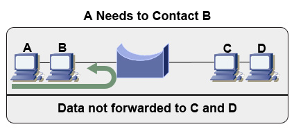
This also effectively gives us two separate collision domains. This will help cut down on data collision, which is a major cause of network latency. Note that in the above example, computer A sends information to the bridge first, which makes the decision to route the request to computer B, while filtering the data out of the segment on the right.
Things to Remember About Bridges
-
- 1. Bridges provide switching via comparing destination MAC addresses found in the data being sent to MAC addresses stored in its tables.
-
- 2. If the source MAC address is not already known, the bridge creates a new entry in the MAC address table with the source port. This will be used for future switching operation.
-
- 3. If the destination MAC address is not known by the bridge, a broadcast will be sent to all segments in a process called flooding. Note that a broadcast is not sent out in the port the data was received on.
-
- 4. If the bridge determines the destination MAC address is not from the same network segment as the sending device, it will forward the data to the appropriate segment.
Layer 2 Switches
Layer 2 switches are essentially the same as bridges, only they have multiple ports and can use microsegmentation to decrease collisions and increase throughput. They also have support for full-duplex operation and spanning tree protocol (STP).
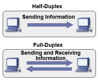
Full-duplex operation enables devices to have support for both receiving and sending information at the same time. This eliminates the problem of data collision altogether. Keep in mind that if a device such as a hub were used, full duplex operation could not be possible because hubs lack microsegmentation.
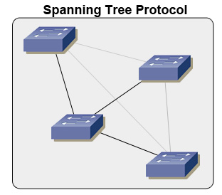
Lastly, switches use what is called spanning tree protocol. Spanning tree protocol is used to help prevent loops from forming. Imagine that switch A forwards data to switch B, since it is unsure where the data should go. Switch B isn’t sure either, and forwards the data back. This creates a never ending loop in theory, but thankfully we can make use of STP. In the example below, you can see that there are four physical links maintained, while two of the links are purely logical- they do not technically exist to the switches.
To counteract the threat of loops, switches send messages called bridge protocol data units, or BPDUs, out every port to let other switches know if its existences. Redundant paths are then shut down through port blocking, and we result with a path free of loops. (These paths can be opened again, however, in case a line goes down and the redundancy is needed.) In the example below, you can see that there are four physical links maintained, while two of the links are purely logical- they do not technically exist to the switches.
Layer 2 Switch Modes of Operation
But what sets them apart from bridges even further is that they can operate in three different modes- Store-and-Forward, Cut-Through, and Fragment-Free.
-
- 1. Store-and-Forward is the method with the slowest operation speed. This is due to the fact that it checks incoming frames of data for integrity. If the frame has errors, it is discarded. Otherwise, it is sent to its destination. This error checking can be quite costly to network performance, however.
-
- 2. Cut-Through switching is considered to be the bare minimum- and thus much faster. It only requires that the beginnings of the frame up to the destination MAC address be read before the frame of data can pass through the switch.
-
- 3. Fragment-Free switching is a modified form of the Cut-Through method. Fragment-free switching filters out collision fragments, which is where the majority of packets errors originate. To do this checking, the switch must wait for the entire packet of information to be received before the filtering takes place. Obviously, it’ll not be as quick as the cut-through method.
A Last Note on Broadcasts and Collisions
Keep in mind that since we have been dealing with layer 2 devices, we do not divide the broadcast domain with these devices. Only a router can divide a broadcast domain. As for collision domains, each of these devices creates more of them (this is a good thing). As for hubs and repeaters, they only extend the collision domain.
Also keep in mind that if a frame is bearing the format of FFFF.FFFF.FFFF, it will be automatically received by all NICs on the network, as this is, in fact, a broadcast address in hexadecimal.


This sit is ver useful
This site is very useful for networking people
nice info :